 STANDARD CAM PROFILING
NOTE: This page was revised on August 14, 1997 to change the
working origin to be the center of the cam shaft, NOT the pivot
point. Revised software allowed the inclusion of a straight line motion
definition. Using the cam shaft center as the origin makes more sense
now
that lever and straight systems are both available. I have amended this
page to include a definition for describing straight line action and
also
made some other minor changes. If you have copied this page in the
past,
please be sure to update it.
CONTENTS: · Introduction
· Conventions · Required
Parameters · Examples · Order
Form
INTRODUCTION
This is a limited standardized approach for describing the
parameters required to produce a cam profile for a plate or box cam
(edge
or groove profiled cam). In some special cam applications, our limited
method of describing the requirement may not be applicable. In such
cases,
we ask that a generally accepted form of documentation be submitted to
us for quotation.
As a quick test to know if your particular cam requirement can
utilize
our description format, each of these items must be true:
-
The cam is either a plate or box type cam, (edge profile or grooved
face;
the output motion acts in a plane perpendicular to the axis of cam
rotation)
-
The cam follower system consists of a pivoting lever or straight line
action
with a rolling type cam follower
-
The cam follower diameter is no larger than 2.0 inches.
-
The maximum cam radius is 12 inches, (300 mm), or less.
-
The cam has a keyway or other distinguishing feature to use as a cam
rotation
angle datum.
Please note that our format is not restricted to the use of our
standard
cam and lever components. Any pivoting lever or straight line rolling
follower
design can be used within the above constraints. Presently, we only cut
plate and box type cam profiles. Not counting barrel cams, ( that are
often
used inside rotary indexers), edge and groove cams are the most
commonly
used types for production machinery. We will add barrel cam profiling
capability
in the future, (and standardized components for them as well),
depending
upon customer interest.
This document is not intended as a design guide nor does it
address
general engineering practices that must be applied to any motion
control
model to verify that it will reliably work as intended. The user should
be capable of analyzing elementary kinematics, work, shock loading, pressure
angle, requirement for precision, etc. and have the experience to
identify
whether or not the specific application at hand requires careful
consideration
of any. The philosophy contained herein reflects our experience in
fabricating
cam motion systems for production machinery and what we have found to
be
the easiest method to do so.
Introduction
· Conventions · Required
Parameters · Examples · Order
Form
CONVENTIONS
DATA ARCHIVING
After we cut a new customer cam profile, we archive the data that was
used
to produce it. Because of this, there is no programming charge for
repeat
orders. The profile data is uniquely identified with the customer's
name,
the cam name, the cam drawing number and revision notation. Unless we
receive
design information to confirm a repeat order, we will assume that the
archive
data is correct. In an effort to help prevent disasters, we suggest
that
the original ordering information, in the format described below, be
saved
by the customer and re-submitted with a repeat order. In this way,
there
will be no uncertainty that we are indeed cutting the most recent
design
revision.
COORDINATES
We use a standard X-Y Cartesian coordinate system with X as the
horizontal
axis positive toward the right of the page and Y as the vertical axis
positive
toward the top of the page. We treat the cam shaft center as
the
X-Y origin. Using ordinate dimensioning, dimensions to features to the
left of the origin or below the origin would be indicated as negative
numbers.
Conversely, positive numbers will be interpreted to mean that the
features
are above or to the right of the origin. All measurements may be in
inches
or millimeters. (For brevity, we have shown all examples herein using
inches.)
ANGLES
Angles are measured in degrees. In keeping with general mathematics
practice,
physical angles, pertaining to the GEOMETRY defining a CAM LEVER or
GEOMETRY
defining a STRAIGHT LINE of ACTION, are described as positive in a
counter-clockwise,
(CCW), direction using the positive X axis direction as zero. Negative
angles, where appropriate, are taken as clockwise, (CW), from zero. (Up
is 90 degrees, left is 180 degrees, down is 270 or -90 degrees, etc.).
CAM ZERO
When describing the angular position of a cam, (it being the ANGULAR
INPUT
function of the system), the zero position could be dictated to be any
orientation and the direction of rotation could be either clockwise or
counter clockwise from that datum. Most machine cams are keyed and, (as
best we know), a cam shaft key way at a 12:00 o'clock position is
generally
employed as the zero angle position. Therefore, for keyed cams, the
motion
profile assumes the zero cam angle position to have the key at the
12:00
position. This is independent of the customer's actual cam shaft
orientation
or definition of zero angle. Example: Given a horizontal cam shaft and
a design cam shaft zero that places the key way pointing to the right
while
viewing it in a 'proper', (gravity pointing down), elevation view, the
order form would be filled out as though one were looking at that same
view but with it rotated counter-clockwise 90 degrees to thus display
the
key way at the 12:00 position.
For cams that have no key, we would prefer that a drawing be
supplied
to us. Some feature of the cam must be designated and used to define
the
zero position. This feature must be described adequately so that there
is no confusion as to what it is, (unique hole size, or at a unique
radial
dimension, etc.). If there are no unique features but several in a
symmetrical
array, (i.e. attachment holes on a bolt circle), we will assume one of
them to be the key position at a 12:00 o'clock position on our geometry
format. In such cases, we will engrave a mark on the cam to designate
the
key position.
DIRECTION OF ROTATION
For standard machine cams, (ours or anybody's), the face opposite the
hub,
(which is also the finished face of our standard cam blanks), will
receive
a stamping of the cam drawing number and an arrow indicating direction
of rotation, (unless we are explicitly instructed not to do so).
Therefore,
for the purpose of indicating the direction of rotation on our form,
the
cam hub is assumed to be DOWN, (far side, away, into the paper, etc.).
For cams with no hub, the side of the cam as described on the form will
receive the engraved direction arrow as it was indicated on the form
diagram.
The notation CW for clockwise and CCW for counter-clockwise is expected.
Introduction
·
Conventions · Required
Parameters · Examples · Order
Form
REQUIRED PARAMETERS
Three groups of data are needed to describe the cam design in our
format:
-
Timing - Position of output lever or relative straight line follower
position
versus angle of cam rotation
-
Lever geometry or straight line action parameters
-
Supplementary information
TIMING
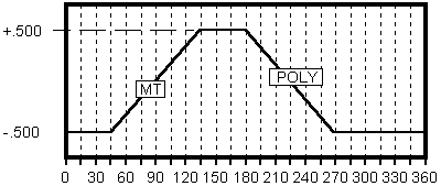
Timing List
We use a timing list in lieu of a timing chart. A timing chart would
look
like this:  Note: It is generally accepted practice for timing charts to depict
rises
and falls as straight lines even though the actual motion would be
represented
by a curve.
Note: It is generally accepted practice for timing charts to depict
rises
and falls as straight lines even though the actual motion would be
represented
by a curve.
Traditional cam timing charts normally relate cam radius
to cam
rotation angle. We believe that, for pivoting arm follower systems, output
lever position is the better parameter to relate to rotation
because
it IS the output function of the system not the cam radius. (For
straight
line follower systems, the relative position of the follower is the
output.)
In the above chart, we have substituted lever position for cam radius.
For a pivoting arm follower system, converting timing from a chart
format
to a list format is straightforward. Each line entry consists of an
ANGLE
of cam ROTATION, the LEVER POSITION at that angle, and the type of
MOTION
to occur between that point of rotation and the next. Each line on the
list can be considered as a 'motion segment'. In summary, each line
entry
must have:
-
The starting cam rotation angle for a motion segment
-
For pivoting systems, the relative position, (explained in detail
below),
of the output lever at this cam rotation angle
OR -- for straight line follower action systems, the relative position
of the follower itself at this cam angle
- The type of motion to be profiled between this angle and the
angle of the
next entry, (or the first entry if this entry is the last one on the
list).
Here is a timing list format for the chart above:
Angle
(degrees) |
Position
(inches) |
Motion
(Abrv.) |
| 57 |
+.922 |
dwell |
| 142 |
+.922 |
4567 |
| 225 |
+.172 |
dwell |
| 312 |
+.172 |
MT |
To further clarify how this works, it may may helpful to consider that
the angle and position data are exactly the coordinates of the points
one
would use to draw a timing chart. The timing chart is simply a
set
of lines drawn between those same coordinates. We have
additionally
chosen to list the motion type of a given segment associated to the
angle
where it starts
LEVER POSITION for PIVOTING ARM FOLLOWER SYSTEMS
For a pivoting arm follower system using our standard cam levers or
anything
similar to them, there is a following arm and an output arm. We define
the position of the output arm as a deflection of the designated design
output point on the lever output arm from an orthogonal datum line
passing
through the center of the pivot point. This datum is either
vertical
or horizontal depending on whether the output lever is oriented in a
generally
vertical or horizontal attitude respectively. For pivoting arm follower
systems only, we make the assumption that the desired output motion
acts
perpendicular to the datum, (this is NOT assumed for straight line
systems).
Although we do not need explicit cam radius information, it must be
noted
that there is a physical limit for any system as constrained by the
maximum
and minimum allowable cam radius that can exist. When designing with
our
standard levers and cam blanks, be sure not to exceed the 'major' and
'minor'
stroke limit for the particular cam and lever system chosen. Please
refer
to Cam Levers for full details.
FOLLOWER POSITION for STRAIGHT LINE FOLLOWER SYSTEMS
For a straight line following system, we first define an arbitrary
neutral
point for the follower and then define the angle of the line of action
passing through that point. (Note: The 'neutral point' concept was used
to allow a definition of a line of action that does not need to pass
through
the cam center.) "Deflections" of the follower from this point along
the
defined line of action can either be positive or negative. As noted for
pivoting systems, do not exceed the physical maximum and minimum
allowable
cam radii.
MOTION TYPES
Designate the type of acceleration profile desired for each rise and
fall
motion. Here is a list of the motion types currently available
and
the abbreviation to use:
    ABRV  MOTION TYPE

     345  3-4-5 Polynomial
    4567  4-5-6-7 Polynomial
    POLY  Special polynomial function, (include formula, 15 degree limit)
      MT  Modified-Trapezoidal
     CYC  Cycloidal
      MS  Modified-Sine
     HAR  Harmonic
  MT/HAR  Modified-Trapezoidal / Harmonic 50/50
  HAR/MT  Harmonic / Modified-Trapezoidal 50/50
  DHAR A  Double Harmonic
  DHAR B  Double Harmonic (reverse function)
CA-CV-CA  Constant Acceleration-Constant Velocity-Constant Acceleration
          (Include the number of degrees for each accelerated portion)
      CV  Constant Velocity
      CA  Constant Acceleration
   Dwell  Dwell
The selection of motion type is dictated by the various dynamic conditions
particular to a given application.  An explanation of each one and the conditions
that favor its use is beyond the scope of this guide.
SYSTEM GEOMETRY - PIVOTING LEVER ARM
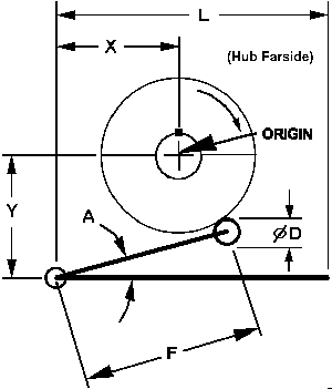
In the above sketch, the variables describe the following
parameters:
| Variable |
Description |
| X |
Horizontal distance from the center of the cam shaft to the
pivot point,
(+ or - ) |
| Y |
Vertical distance from the center of the cam shaft to the
pivot point,
(+ or - ) |
| *F |
Length of Lever Follower Arm |
| L |
Length of Lever Output Arm |
| *A |
*Angle from Lever Output Arm to Lever Follower Arm,
(degrees; can be
negative) |
| D |
Diameter of the Cam Follower |
| M |
Orientation of the Lever Output Arm, (0, 90, 180, 270 - OR
- up, down,
right, left) |
* - Parameters F & A may be omitted if an R. D. Dane Standard Lever
CL4 or CL5 is being used. Simply substitute 'CL4' or 'CL5' for the
parameter
value.
SYSTEM GEOMETRY - STRAIGHT LINE FOLLOWER ACTION
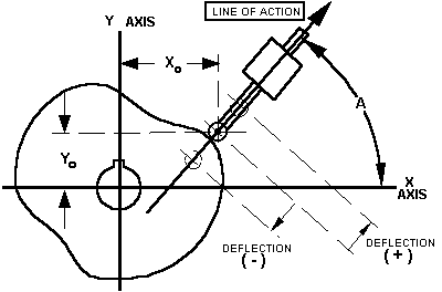
In the above sketch, the variables describe the following
parameters:
| Variable |
Description |
| X0 |
Horizontal distance from the center of the cam shaft to
the
center of the selected neutral follower position, (+ or - ) |
| Y0 |
Vertical distance from the center of the cam shaft to
the
center of the selected neutral follower position, (+ or - ) |
| A |
Angle from the positive X axis direction to the direction
of
the positive line of action, (degrees; use a positive value) |
| D |
Diameter of the Cam Follower |
|
|
SUPPLEMENTARY INFORMATION
The only remaining information needed is the following:
-
Company Name:
-
Contact Name:
-
Cam Drawing Number:
-
Cam Drawing Name:
-
Cam Blank Description or Dane Number
-
Direction of Cam Rotation WITH HUB FARSIDE
Optional:
- If there is no hub, describe a feature existing on same side of
the cam
as that viewed for the parameters.
-
If there is no key way, describe a feature that will serve as the zero
angle position.
Introduction
· Conventions · Required
Parameters · Examples · Order
Form
Example 1 · Example
2 · Example 3 · Example
4 ·
EXAMPLES - Using our format to order cam contours
Example 1
Note: In this example, standard programming and profiling charges would
apply.
Given a lever geometry:
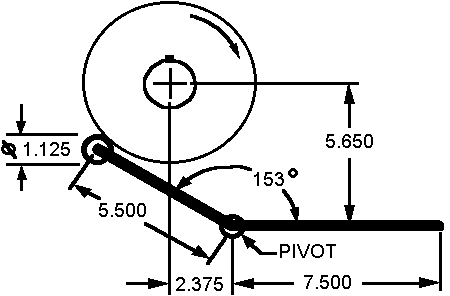
The parameter list would be completed as:
| Variable |
Value |
Description |
| X |
+2.375 |
Horizontal distance from the center of the cam shaft to the
pivot point,
(+ or - ) |
| Y |
-5.650 |
Vertical distance from the center of the cam shaft to the
pivot point,
(+ or - ) |
| *F |
5.500 |
Length of Lever Follower Arm |
| L |
7.500 |
Length of Lever Output Arm |
| *A |
153 |
*Angle from Lever Output Arm to Lever Follower Arm,
(degrees; can be
negative) |
| D |
1.125 |
Diameter of the Cam Follower |
| M |
RIGHT |
Orientation of the Lever Output Arm, (0, 90, 180, 270 - OR
- up, down,
right, left) |
Given this timing requirement for the lever position versus cam
rotation,
(positive=up): 
The Timing List would be completed as:
Angle
(degrees) |
Position
(inches) |
Motion
(Abrv.) |
| 45 |
-.125 |
MT |
| 75 |
+.390 |
CV |
| 135 |
+.500 |
Dwell |
| 225 |
+.500 |
345 |
| 270 |
-.125 |
HAR |
| 315 |
+.390 |
HAR |
The information is completed by including:
-
Company Name: NewCorp
-
Contact Name: Jane Whalen
-
Cam Drawing Number: X-123-4321
-
Cam Drawing Name: Untested Cam
-
Cam Blank Description or Dane Number: SPC-C4
-
Direction of Cam Rotation: CW
Introduction
·
Conventions · Required
Parameters · Examples · Order
Form
Example 1 · Example
2 · Example 3 · Example
4 ·
Example 2
Note: In this example, standard programming charges would apply but
an additional charge would apply to the profiling for non-standard
fixturing,
(3 attachment holes and two dowels) and for cutting a harder material,
(~50 Rc).
Given a lever geometry:
The parameter list would be completed as:
| Variable |
Value |
Description |
| X |
+4.500 |
Horizontal distance from the center of the cam shaft to the
pivot point,
(+ or - ) |
| Y |
+4.250 |
Vertical distance from the center of the cam shaft to the
pivot point,
(+ or - ) |
| *F |
5.000 |
Length of Lever Follower Arm |
| L |
9.000 |
Length of Lever Output Arm |
| *A |
-12 |
*Angle from Lever Output Arm to Lever Follower Arm,
(degrees; can be
negative) |
| D |
1.000 |
Diameter of the Cam Follower |
| M |
270 |
Orientation of the Lever Output Arm, (0, 90, 180, 270 - OR
- up, down,
right, left) |
Given this timing requirement for the lever position versus cam
rotation,
(positive=right): 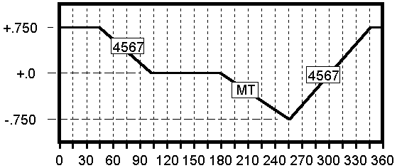
The Timing List would be completed as:
Angle
(degrees) |
Position
(inches) |
Motion
(Abrv.) |
| 45 |
+.750 |
4567 |
| 105 |
0 |
Dwell |
| 180 |
0 |
MT |
| 255 |
-.750 |
4567 |
| 345 |
+.750 |
Dwell |
The information is completed by including:
-
Company Name: NewCorp
-
Contact Name: Jane Whalen
-
Cam Drawing Number: X-123-4322
-
Cam Drawing Name: Another Untested Cam
-
Cam Blank Description or Dane Number: .625THK X 7.0 OD X .750Bore, No
Hub,
AISI #4130 Pre-Hardened 50 Rc
-
Direction of Cam Rotation: CCW
-
Identify Face UP: Counter-bores UP
-
Substitute Datum : Use any one of the counter-bored holes as zero
Introduction
·
Conventions · Required
Parameters · Examples · Order
Form
Example 1 · Example
2 · Example 3 · Example
4 ·
Example 3
Given a lever geometry:
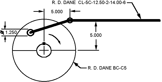
The parameter list would be completed as:
| Variable |
Value |
Description |
| X |
+5.000 |
Horizontal distance from the center of the cam shaft to the
pivot point,
(+ or - ) |
| Y |
+5.000 |
Vertical distance from from the center of the cam shaft to
the pivot
point, (+ or - ) |
| *F |
CL-5C |
Length of Lever Follower Arm |
| L |
12.500 |
Length of Lever Output Arm |
| *A |
CL-5C |
Angle from Lever Output Arm to Lever Follower Arm,
(degrees; can be
negative) |
| D |
1.250 |
Diameter of the Cam Follower |
| M |
0 |
Orientation of the Lever Output Arm, (0, 90, 180, 270 - OR
- up, down,
right, left) |
Note that the output lever length, (12.500), is still included on the
list.
In this case, there are two holes specified on the R. D. Dane CL-5C
lever
making it uncertain as to which is the actual output lever design
length.
However, it will be good practice to include this length even when only
one hole is specified in the lever order number.
Given this timing requirement for the lever position versus cam
rotation,
(positive=up), and a notation for modified trapazoidal motion: 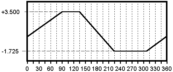
The Timing List would then be:
Angle
(degrees) |
Position
(inches) |
Motion
(Abrv.) |
| 90 |
+2.500 |
Dwell |
| 135 |
+2.500 |
MT |
| 225 |
-1.725 |
Dwell |
| 310 |
-1.725 |
MT |
Considering the size of this upward position value, it would be wise to
check that the stroke is within limits using a BC-C5 box cam blank and
a CL-5 lever. Looking back to the listing on CAM
LEVERS, the value of concern is the 'MINOR' because the upward
stroke
in question brings the follower toward the cam hub. The value listed in
this case is 3.500. Because lever length 'L' is 12.500, the adjusted
limit
is proportioned by multiplying it by the ratio 12.5/17.0. This results
a value of 2.573 indicating that our stroke of 2.500 is safe.
The information is completed by including:
-
Company Name: NewCorp
-
Contact Name: Jane Whalen
-
Cam Drawing Number: X-123-4323
-
Cam Drawing Name: A Box Cam, .75 track depth
-
Cam Blank Description or Dane Number: BC-C5
-
Direction of Cam Rotation: CW
Introduction
·
Conventions · Required
Parameters · Examples · Order
Form
Example 1 · Example
2 · Example 3 · Example
4 ·
Example 4
Given a straight line geometry:
The parameter list would be completed as:
| Variable |
Value |
Description |
| X |
+3.500 |
Horizontal distance from the center of the cam shaft to the
neutral
follower position, (+ or - ) |
| Y |
+2.250 |
Vertical distance from the center of the cam shaft to the
neutral follower
position, (+ or - ) |
| F |
---- |
(n/a leave blank) |
| L |
---- |
(n/a leave blank) |
| A |
40 |
Angle from +X axis to the positive direction of line of
action, (positive
degrees) |
| D |
1.500 |
Diameter of the Cam Follower |
| M |
---- |
(n/a leave blank) |
The radius to the center of the follower at the neutral position is:
(3.5^2
+ 2.25^2)^.5 = 4.161
Given this timing requirement for the relative follower position
to
the above neutral point versus cam rotation, (please ignore the shape
of
the cam shown in the geometry picture):
The resulting follower stroke is 1.000 inches. Note that
because
the line of action is not through the origin, the center to center
major
and minor cam radii are NOT 4.661 and 3.661 !! The center to center
actual
major and minor will be 4.657 and 3.665. Though, it it not necessary to
supply these computed values to order our contouring service it is
encouraged
that they be checked to insure that they are possible within the
physical
constraints of the cam blank. In this case, 4.657 is okay for an SPC-C5
because, with a follower radius of .750, there will be a minimum of
.093
of extra material.
The Timing List would then be:
Angle
(degrees) |
Position
(inches) |
Motion
(Abrv.) |
| 45 |
-0.500 |
MT |
| 135 |
+0.500 |
Dwell |
| 180 |
+0.500 |
POLY |
2.2X^2 -12.3X^3 +18.6X^4 +8.2X^5 -27X^6 +11.3X^7 |
| 270 |
-0.500 |
Dwell |
Any polynomial series function up to 'degree' 15, (currently), can be
used
to define special motions.
The information is completed by including:
-
Company Name: Widjo Wacka
-
Contact Name: Franky
-
Cam Drawing Number: X-123-4323
-
Cam Drawing Name: A Strange Cam
-
Cam Blank Description or Dane Number: SPC-C5
-
Direction of Cam Rotation: CW
Introduction · Conventions
· Required Parameters · Examples
· Order Form
Return to R. D. Dane home page
Date modified - August 14, 1997 (major)
Modified November 12, 1997 (cosmetic)
Modified July 14, 1998 (minor additions)